There is also a PDF version here which might be easier to read because it has a bit more formatting.
This document describes the life cycle process used by the ABC project, the motivations for that life cycle, and how that life cycle was determined and implemented. Our primary goal is to document ABC’s process so other teams can gain a better understanding of it and use it to help develop processes for other teams. Our secondary goal is to continue documenting and crystallizing ABC’s process for use within the ABC team. The ABC project was a specific project for the XYZ company, but names have been changed and any proprietary materials removed. This makes the material available to a wider audience, with only a few holes.
The ABC project’s process has several salient characteristics that impact how it can be described. (1) It is currently in use within XYZ. (2) It has had several months to work our rough edges. (3) It was primarily guided with a core set of goals. (4) It is principally based on an integration of several documented and mainstream development practices. So to describe the process we can alternate from the very concrete (“the ABC team does this”) to the more general (“Booch suggests doing this”). We can also leverage existing writings and just describe the differences from those writings and how they were integrated into the ABC process. We hope that connecting these differing abstraction layers and perspectives will both make the process more understandable and make the concepts more applicable to other teams.
1.1 Prerequisites
This document refers directly and indirectly to many books and to the ABC documentation. The specific books are discussed in the following chapter, as are the sources for ABC documentation. Although many of these sources can be read concurrently with this document, at least a few of them should be reviewed ahead of time or the material within here will be difficult to understand or put in context. It is recommended that you are familiar with the following resources.
Most XYZ readers will have had SELECT training, but if you have not had this training you should review one of the following SELECT documents:
|
Component-Based
Development for Enterprise Systems |
Allen+F 98 |
|
Object-Oriented
Analysis & Design for Client/Server Development |
SELECT-1 |
You should be familiar with at least one of the following (preferably at least the first):
|
Software
Project Survival Guide |
McConnell 98 |
|
Surviving
Object-Oriented Projects, A Manager’s Guide |
Cockburn 98 |
|
Object
Solutions: Managing the Object-Oriented Project |
Booch 96 |
It would be good if you were familiar with certain ABC resource locations. Three very important ones are:
ABC Development Process …/public/ABC/Development/Process
ABC Development Progress …/public/ABC/Development/Progress
ABC Development Standards …/public/ABC/Development/Standards
ABC Learning Resources …/public/ABC/Learning
These locations are cross-linked to other resources in ABC and OTC directories. Currently the ABC web-site is not a major resource. Most ABC process documents will be directly referenced or incorporated into this document as needed, but the above locations will have more details and related documents.
1.2 Process Focus
The discussion within this document of the ABC project and team is primarily focused on the development effort beginning in January, 1998. The ABC feasibility and preliminary analysis work was done before that time period by a different team using different processes. These previous processes and their deliverables are considered (abstractly) part of the ABC development process, but these previous processes are not described in any detail. Also, no part of the deployment process (e.g. hardware considerations) is being covered in this document.
1.3 Related Resources
The best resources to use with this document are the people at XYZ that have experience with ABC and its process. Foremost this would be the ABC team. It would also include OTC team members and many of the supporting organizations with IS: DA, DBA, QA, and so on. As the process is described further some of these related resources will be more obvious.
1.4 Attributions
This document is a merger of a general approach to OOIS development (as described by several sources and integrated into a single process by ChiMu employees) and the specifics of the ABC project. The main overall process described herein originates from previous ChiMu work and copy-written materials, and this document maintains those copyrights.
ABC has a development process different from previous projects done by the DEF group. The differences in the process were caused by ABC’s use of several new techniques, tools, and approaches:
1. Use Cases and OO models to help communicate requirements
2. An OO programming language for implementation
3. New tools for analysis and development
4. A more formal 3-layer architecture
5. A recently formed and larger team than on preceding projects
These new techniques and tools were recommended inputs into the ABC project/process in the view that they would have benefits both to the ABC project itself and to subsequent XYZ projects that followed ABC. All the new features were introduced at the very beginning of the team’s formation, and the team needed to learn and evaluate the utility of these new features during the course of the project.
The primary goals of the ABC development process were to (1) support the ABC team in developing a high-quality application that met the customers’ needs, (2) improve the quality of the development process itself, by (3) incorporating the new features mentioned above. These goals are summarized in the ‘Vision Statement’ for ABC:
The ABC project will develop an application that meets basic XYZ needs for quoting, booking, and invoicing, and will begin deployment of the application by January 1st, 1999. ABC will be developed with a strong attempt to use an effective, predictable, and repeatable Use-Case based process and Object-Oriented architecture. ABC will be among the best designed and documented software XYZ has ever built: a base for continued development and a good model for future software.
Such a vision statement is part of the ABC process and is described in [McConnell 98 § 7].
2.1 Sources
The development process ABC uses is an integration of many different sources, and this document will refer to and leverage these high-quality sources as much as possible. This section identifies most of the major sources and where to get them.
The ABC development process came from many sources and forms. The sources include:
• Previous experience of the ABC team
• General XYZ standards
• Standard industry knowledge and (sometimes) practice
• Externally provided training and mentoring (e.g. ChiMu, SELECT, <Java Training>, Tech-ONE)
• Characteristics of the development tools (e.g. SELECT, Visual Cafe, ERWin, SourceSafe)
And the forms include:
• Written knowledge
• Group experiences
• Formal training
• Intra-team and inter-team interaction
• The “organic” growth from the above combination
Of these sources and forms, only the written knowledge from the general industry, external training, and the project itself is easily referenced. This will provide a large bulk of knowledge about ABC, and is what this document will be using. Alone, though, it will not enable a full understanding of the process, so it would be beneficial to try to take advantage of other resources. For example, to utilize the related resources mentioned in the overview: the people at XYZ familiar with ABC. Other forms of cross-team communication (informal, presentations, combined working) would also be beneficial.
These written sources include documented parts of the ABC process and documents of more general origin.
ABC Process Documents
Certain resources were formally part of the ABC process and the day-to-day or training activities of the project. Most of these types of documents will be referred to within this document, but you may also want to refer to some of them directly…
ABC Development Process …/public/ABC/Development/Process
ABC Development Progress …/public/ABC/Development/Progress
ABC Development Standards …/public/ABC/Development/Standards
ABC Learning Resources …/public/ABC/Learning
Specific References
|
MeterRock
Definitions |
…/Standards/ |
|
ABC
Progress Flow |
…/Progress/ |
|
ABC
Risks |
…/Progress/ |
|
ABC
Vision Statement |
…/Standards/ |
|
ABC
Increment Template |
…/Process/ |
|
ABC
Flow Template |
…/Process/ |
|
ChiMu
Guidelines |
…/Standards/ |
External Sources
External sources have material that was (or could have been) visibly integrated into the ABC process. In some cases, a technique was extracted and used directly with little modification (e.g. “Risk Management” from [McConnell 98] ). In other cases, the overall flavor of an approach was incorporated if not the specifics (e.g. “Conceptual Integrity” from [Brooks 75] ). And in some cases, no conscious attempt to use an approach was made but they still provide a very good description of the process or context for the process.
To make the external references a little more accessible, they are broken into a short, medium, and long list[*]. The short list contains five books that are mandatory reading for fully understanding the ABC process and how to generalize and apply it to other projects. The medium list is also extremely important, but is more a broadening of the perspectives within the short list than directly applicable. The long list contains much more depth. Finally, there is also a short technical list that is not directly on process but may help understanding of OO systems in general.
Short List
|
Component-Based
Development for Enterprise Systems |
Allen+F 98 |
|
Object
Solutions: Managing the Object-Oriented Project |
Booch 96 |
|
Surviving
Object-Oriented Projects, A Manager’s Guide |
Cockburn 98 |
|
Applying
UML and Patterns: An Introduction to Object-Oriented Analysis and Design |
Larman 97 |
|
Software
Project Survival Guide |
McConnell 98 |
Medium List
|
The
Mythical Man-Month |
Brooks 75 |
|
Controlling
Software Projects |
DeMarco 82 |
|
Understanding
UML: The Developer’s Guide |
Harmon+W 98 |
|
The
Object Advantage: Business Process Reengineering with Object Technology |
Jacobson+EJ 95 |
|
How
to Run Successful Projects |
O’Connell 94 |
Long List
|
Constantine
on Peopleware |
Constantine 95 |
|
201
Principles of Software Development |
Davis 95 |
|
Peopleware:
Productive Projects and Teams |
DeMarco+L 87 |
|
Managing
the Software Process |
Humphrey 89 |
|
Debugging
the Development Process |
Maguire 94 |
|
Dynamics
of Software Development |
McCarthy 95 |
Short Technical List
|
Design Patterns: Elements of Object-Oriented Architecture. |
Gamma+HJV 95 |
|
UML
Distilled: Applying the Standard Object Modeling Language |
Fowler 97 |
|
A
Good Architecture for Object-Oriented Information Systems |
Fussell 96 |
|
UML: Unified Modeling
Language, Version 1.1 |
Rational 98 |
2.2 Major Concepts
There are many important concepts in the ABC process, and these will be described in subsequent sections. The following is a list of “buzzwords” that apply (or we would like that they apply) to the ABC process. This is provided as a first exposure to some of the ABC process concepts.
|
Architected |
The desired architecture of the system is identified and verified early in the development process |
|
Blueprinted |
A specification of what is to be built and how it will be built is generated as part of the process. |
|
Coordinated |
Team members are actively informed about the state of the project and supported in intra-team and inter-team communication. |
|
Decentralized |
As much as possible, task organization is moved to the smallest effective management unit. |
|
Documented |
The process itself is documented as much as possible: first informally and then more formally as that becomes possible and useful. |
|
Generalized |
Common functionality is extracted and generalized into frameworks and libraries usable by multiple parts of the application. |
|
Incremental
|
The system is divided into pieces that can be developed subsequent to each other. |
|
Iterative |
Particular parts of the system are explicitly refined over the life of the project. |
|
Measurable |
The state of the project is visibly measurable, and estimations can be compared to actuals. |
|
OO |
Most of the technical techniques are object-oriented (although this has only a limited impact on the overall process). |
|
Public |
Information about the project is public to all the team members |
|
Reviewed |
Each development cycle includes a review and improvement process to improve the process. |
|
Risk-managed |
Project risks are actively identified, ranked, and managed |
|
Self-managing |
If coordination and lead activities are stopped, the development team will continue the development process on their own accord. |
|
Skilled |
Tasks generally require specific skills and are not immediately interchangable between team members. |
|
Standardized |
There is a continuous progression from guidelines to standards as the team decides |
|
Tool-supported |
As much as possible, development activities are supported by tool-based automation |
|
Unified |
It should appear that it is exactly one team, even just one developer, which is building this system. All the different aspects of the process should be conceptually integral to each other: they are just different views of the same process. |
|
Use-case
based |
Use-cases are one of the techniques used for gathering |
|
Verified |
All deliverables and processes are tested for their value to downstream customers. |
The following chapters will detail what all these buzzwords mean to ABC and how they fit into the process.
This chapter describes the ABC process starting from a macro-level process and progressing down to a granularity that includes the details of incremental development, use cases, and high-level architecture. All together this gives a good feel for the overall high-level process. The next chapter will delve into team structure, coordination, and a much more detailed process.
Organization
Most sections with this chapter and the next start have a standard structure. Each of them that starts with a process diagram, walks through that diagram to describe its salient characteristics, and then defines any new terminology. This is followed by a discussion of the process concepts. Finally the section can cover the specifics of the actual ABC process and contrast it to the described process.
Notation Description
The following notation is present on the diagrams within this chapter. Further graphical items will be defined when they are first encountered.
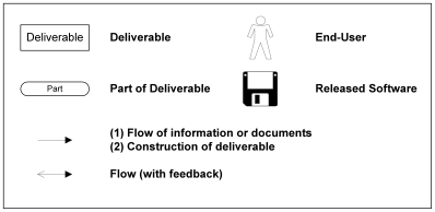
The following are some important definitions for the above:
|
Work Product |
“The tangible result of work performed.” [McConnell 98] |
|
Deliverable |
A defined work product that will be used as the input to another process or released outside the team. Deliverables are documented to describe what receiving parties can expect of them, and they are tracked as part of project management. “Any work product that must be delivered to someone other than the work product’s authors.” [McConnell 98] |
|
Process |
A collection of tasks/work that produce deliverables. In this document, processes are performed or controlled by humans: they have the same meaning as in a physical data flow diagram. See [DeMarco 78] |
Note that the icon for a deliverable is a rectangle of the particular size and with the textual format indicated above. Rectangles that have other sizes, shapes, and textual formatting do not usually have the meaning of a deliverable, but may instead be just for visual grouping, to indicate a subsystem, or to identify some interesting entity that will later.
3.1 Macro-level Process Model
The macro-level process is abstract up to the point of approximate coincidence with almost all software processes. See the following references to correlate this model with other macro-level processes: [Allen+F 98 § 12.3], [Booch 94 § 3 ], and [Larman 98 § 2.3].
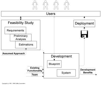
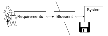
Walkthrough
Walking through the above diagram, first the feasibility team works with the users to conceptualize and evaluate the feasibility of a software project. This feasibility study includes identifying the users’ requirements, a preliminary analysis of what building a suitable system would entail, and estimations of the cost and time required. The feasibility study primarily returns a “GO” or “NO GO” answer, but it also produces deliverables that can benefit the development process or other projects that are considering similar requirements. If the feasibility study say “GO” we move into the next stage.
Next, the development team begins development of the software systems. During development they do more detailed analysis and system design to create a much more precise and accurate blueprint of what they will be building. This blueprint is then used to construct the system. When the system meets the detailed requirements it can be moved to deployment.
Finally, deployment integrates the system into the users’ business process.
Definitions
One unusual deliverable in the above diagram is named the “blueprint”. Blueprints will be covered more in upcoming sections, but for now a short definition is:
|
Blueprint |
A specification of what a user desires and what a development team will build. |
The term “blueprint” should give the general feel of how an architectural blueprint fits into the building process and not be associated with its actual physical manifestations.
ABC Specifics
This macro-level process is instead innate to ABC’s project lifecycle and current activities[†]. ABC is currently developing a system based on the feasibility study in 1997, and that development is for deployment to XYZ in 1998. ABC has deliverables from the feasibility study in the forms of the Provision analysis model, high-level use cases, some ER models, and several other forms of requirements. We also have an estimated completion date based on business requirement and previous experience developing these types of systems with this approach[‡].
3.2 Incremental Development
The first important detailing of the macro-process is to include the concept of incremental development. Incremental development changes the development stage by breaking it into portions (increments) that produce system deliverables before the final deployment stage. These intermediate deliverables can be released to the end-users to get feedback on whether it is heading in the right direction to meet their needs. More importantly, the process of building these increments enables the development team to experience a full development cycle without using all the project lifetime. This allows the development team to:
• Learn and experience the full development process on manageable amounts of functionality
• Correct mistakes in the architecture, tools, design, and processes
• Discover what you don’t know you don’t know (WYDKYDK)[§] earlier
• Produce truer, fact-based, estimates of the project’s timeline
• Monitor progress more precisely
• Develop a repeatable rhythm
For other perspectives and details on incremental development, look at [McConnell 98 § 5, 11, 12], [Cockburn 98 § 4], and [Allen+F 98 § 12.3]. Note that McConnell uses the term “Stage” in approximately the same meaning as ABC uses the term “Increment”. There is also some variation in whether an increment includes continued requirements and analysis work, or only design and construction. For ABC an increment explicitly includes continued requirements work.
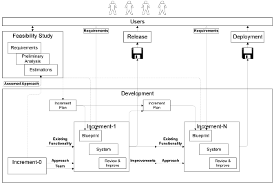
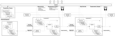
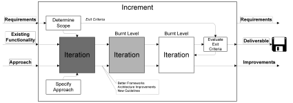
Walkthrough
In the incremental process diagram the feasibility study and deployment stages are the same as in the macro-level process without incremental development. The changes are all to the Development stage which is now broken into a number of increments (shown as 2+1) that are each as complete as the previous whole development box.
Increments
The difference between the increments and the previous whole development is that each increment will only deal with a portion of the whole, deployed system. Each increment may be restricted by only dealing with: (1) a subset of the use cases, (2) a limited amount of business rules within a set of use cases, (3) common cases or exceptional cases, or (4) a simpler technology architecture than will ultimately be required. Portioning the increments requires proper planning, so one of the first tasks development does is to plan the sequence and contents of each of the increments. All the increments do not need to be fully specified (the work in the increments will help to fully-plan later ones), but an overall concept of increment progression should be thought out and the immediately subsequent increment needs to be fully determined. See the following discussion subsection for more on increment progression.
This increment plan is then used along with the other requirement sources to define the blueprint (the covered functionality) and the other exit criteria (e.g. whether or how the database is used) of a given increment. As the increments progress, the increment plans for subsequent increments can be detailed and refined.
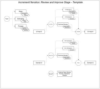
Review & Improve
The next major change is within the increments themselves. Each increment has a Review & Improve process within them. This is to support the continued refinement and improvement the incremental cycles will allow. During each increment, the team reviews the code, designs, tools, architecture, and processes to see what should be improved. All necessary changes should made as soon as possible so they are available as part of the existing functionality for the subsequent increment. The team should also revisit all the standards to correct and further document them based on the increment’s experience. Although this might be similar to a post-mortem for a project, it has one obvious difference: these improvements clearly benefit the current team because they will be used in all the subsequent increments. Although some of these activities will be done as part of the increment’s system development, it is important to identify that they must be done before the increment has fully completed.
Increment-0
A final, very notable change is that there exists an Increment-0 even before the feasibility study has been completed. Increment-0 is an increment focused on learning and experiencing the approach that will be used to develop particular types of systems. Increment-0 can be started before the feasibility of a particular project is verified, especially if the approach used will be significantly different from what a team has experienced before. It is more of a team training and preparation phase than part of any particular project, but it should be considered mandatory before entering project development. If the approach to be used is similar to previous approaches for the team, than the Increment-0 should be very short. Increment-0 should have a deliverable like any other increment, but it should be very simple in breadth and should be considered a throwaway.
Increment-0 can also help the estimation process for the feasibility stage by providing actual (although preliminary) data for a new development process. Since the goal of feasibility estimates is to correctly predict the actual time the project will take, this initial data is very important.
Summary of Walkthrough
Feasibility and Deployment were unchanged, but development stage is now divided into planned increments that tackle only part of the full system’s complexity and these increments can build upon both the code and the processes developed in the previous increments.
Definitions
|
Increment |
(1) A portion of a system’s functionality that is built together. Increments limit immediate scope, build upon previous work, and support changes in goals, understanding, and processes during a full project’s lifecycle. (2) The development effort used to build an incremental work product. In the later context, an Increment has defined deliverables and other exit criteria, which will be reached by the processes within the increment. |
|
Increment-0 |
An increment focused on preparing the development team to use a particular approach for developing systems. This includes both individual training/experience and group training/experience. |
|
Increment Product |
A work product resulting from an Increment’s work. |
|
Release |
An Increment Product that is given to external teams (especially the end users) for their evaluation. |
|
Deployment |
A release that will go into user production: it will be integrated into the business process and used to record business information. Deployments must be subsequently to prevent harm to the business process and loss of information. |
Discussion
Requirement Changes
An important concept is that increments should controllably allow and disallow requirement changes. Requirement changes can come in at the beginning of an increment while the blueprint is still being created, but after that blueprint is externally frozen, all subsequent requirement changes will be considered input to the subsequent increment. This allows the development team to have a stable model to implement, allows the user to change requirements (at specific points in time), and makes the cost of requirement changes more visible to all parties. This last point may be the most important, for it makes sure requirement changes are visible and their benefits are evaluated against the time and other costs they will consume. Unevaluated changes are the ones that make projects fail: “[A successful project has a] ruthless focus on the development of a system that provides a well-understood collection of essential minimal characteristics” [Booch 94].
Project Management
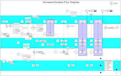
Project management for incremental development is somewhat difficult with current tools. See [McConnell 98] and [O’Connell 94] for suggestions about project management approaches and tools. ABC originally used two Microsoft Project files to manage the detailed internal deliverables and dependencies. One file contained the template for a generic Increment (see […]) including the inputs and outputs from that increment. The main project file contained the full serialized set of increments (and iterations), which was constructed by inserting the template file for a given increment and hooking its connections up. Although this was a workable solution, it was time-consuming and not of the greatest benefit to the team. It was subsequently replaced with the Process-Flow diagram (see the next chapter), but now both are in use for different purposes.
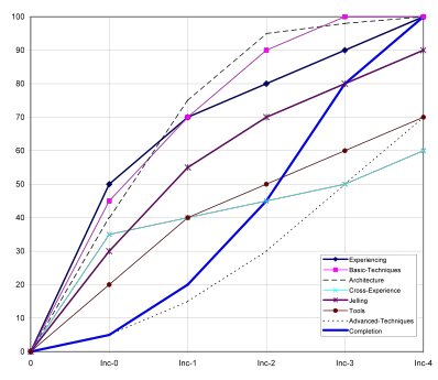
Increment Progression
Each increment focuses on a portion of the completed systems functionality. Planning this progression requires optimizing the growth of the team, the growth of the system’s architecture, and the growth of delivered functionality. The following is a standard increment optimization order that deals with the bigger, longer-impacting issues up front: the team and the architecture. The highest priority in Increment-0 and Increment-is making sure the whole team has learned all the basic techniques they need and has gained experience with the type of system they are building and the development process. Next in priority is doing a good architectural test: building a complete vertical slice of the application with most of the major issues addressed. This should be completed by Increment-1. Next in importance is supporting the jelling process of the team and continued growth in using the development tools and the more detailed processes. By increment-3 all these concerns should have stabilized at a higher level and the team can be focusing on completion of functionality. A visual representation of a four-increment progression might look like the following diagram.
ABC specifics
ABC has been mostly successful in using an incremental development process almost identical to that described here, but it has not become a repeatable process due to some deviations and a limited number of increments progressed through so far. The current increment is likely to establish the full repeatability and rhythm of the incremental process.
ABC had an Increment-0 that focused on the whole team getting a feel for all aspects of the development process on a very small example. This was followed by Increment-1.1, which dealt with creating a booking (and was only single-user). This was followed by Increment-1.2, which further expanded the booking functionality. Finally, Increment-1.3 focused on bringing the database and related activities into the development cycle. Originally this was followed by Increment-2, but that was put on hold as a significant modification to Increment-1 functionality was requested. These requested changes lead to an Increment-1b, which had a similar focus as Increment-1 but different requirements (i.e. a completely different blueprint). Increment-1b brought in the 1.3 database process. As of this writing (September) we have returned to mid Increment-2.
Increment-0
Increment-0 lasted several weeks because of the large amount of technical and process differences for the ABC project, and by the end of the increment the whole team had initial experience in a broad range of new areas as well as how they might fit together. Team members were exposed to almost all aspects of the approach on a limited scale. We also started refining the process to work better in the XYZ and team’s environment.
Unfortunately for time considerations Increment-0 could not be done in parallel to the feasibility study because that study had already been completed. So Increment-0 was chronologically located in the Increment-1 position, which also means it could not be used for the estimating process in the feasibility study. Finally, Increment-0 only superficially dealt with the database and related activities. This was the most significant uncovered part of the process.
Increment-1
Increment-1 continued the bringing-up-to-speed of the whole development team, but it was now oriented to releasable functionality. During this increment development team members started to specialize and increase their skills, and as these skills improved, intra-team organization and dependencies became the biggest issues. These issues will be discussed in subsequent sections.
Increment-1b
Although Increment-1b started in a strange fashion (minor UI changes transitioned into significant functionality changes), it finished much like any earlier increment might. The review and improve process within this increment produced the first complete set of internal deliverables, so the team had developed a much better understanding of the process. This was the first release to include database functionality.
Increment-2
Increment-2 just started as of this writing but it already has a much nicer “wave-front” of subteam progress. It also has the best definitions of deliverables and dependencies, which should make for a relatively smooth increment.
3.3 Use Cases and Conceptual Models
Adding use cases[**] to the development process can produce many changes. First, it simply provides a new tool for communicating with the user and formalizing their needs. Second, it hooks the analysis process into producing an OO conceptual model. Third, it strongly encourages focusing on what a user’s environment needs, instead of what a system can do. Fourth, it can lead to endless debates of what granularity use cases should be, what the difference between a use case and a scenario is, and so on. Of these, the first two are the most important to discuss as part of a development process.
Use cases are used as part of eliciting requirements from the user and creating “blueprints” for the desired system. Blueprints are the collection of documentation that is used to communicate what a user desires and what a development team will build. Blueprints could take any number of forms, and the most important property is that they work: they provide a good (sufficiently precise and accurate) communication vehicle between the development team and the users. ABC’s process uses UI mockups, narratives, use cases, conceptual models, data models, correlation notes, and other requirement documents as part of the blueprint for a system. Some of these documents are more useful than others (UI mockups are by far the most useful) and others are just legacies of the preliminary analysis more than currently active parts of the blueprint deliverable. But all sources are useful until they are superceded by their functional equivalent.
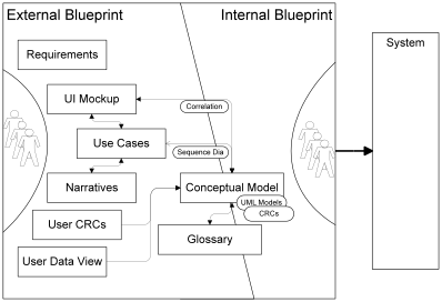
Walkthrough
The whole box represents the entire blueprint deliverable. End users are on the left and developers are on the right. This represents the different perspectives on the Blueprints. Although all of it maters to both sides, much of the development team want it more processed (across the centerline) towards development than in the form the end users use. The diagram is only approximate and a first level simplification[††]: for example, the UI Mockup deliverable progresses from being very loose and user focused to being much more directly applicable for development.
User Requirements
The different deliverables on the left (around the end users) are many of the different tools we used or considered using to elicit requirements from the user. Of these, the top requirements box is for anything not elsewhere classified. The UI Mockup only need to be purely visible mockups: they do not need to be functioning prototypes unless it is to communicate a requirement. Narratives and Use Cases are the main-stream definitions in the resources mentioned above. User CRCs are the results (e.g. CRC cards) of doing Class-Responsibility-Collaboration sessions with the end users (see [Wilkinson 95] and [Wirfs-Brock+WW 90] for more information). ABC does not use this process although it was introduced as part of the Increment-0 training stage. Finally, the User Data View is composed of ER models and similar data models that may be helpful in communicating to some users. These are generally subsumed in the Conceptual Model described below.
Modeling
Running along the centerline are the Conceptual Model and the Glossary. The Glossary contains the business terms for the users and is strongly linked to their daily business terms (and ideally agrees with the narratives). The Conceptual Model is an OO model of the users’ business sufficient to describe what our system needs to understand for it to function (see [Fowler 97a], [Fowler 97b], [Larman 98 § 9.3]). For ABC, the conceptual model includes primarily Class and Sequence diagrams.
Internal
The full internal blueprints would also include architecture, framework, and other considerations but these will be addressed in the next section.
Interconnection and Correlation
All these different deliverables better be describing the same system or we will have serious loss of quality. It is difficult to have a good communication channel when two messages are being mixed together. The deliverable diagram shows the flows and feedback between deliverables, which support verifying they are really describing the same system. Some of these are normal parts of the use case development process: for example, using Sequence diagrams to connect the Use Cases with the Conceptual model. Other of these are commonly unmentioned as part of the development process: for example, the functionality and data in the UI mockups should be verified to agree with the behavioral and information models of the Conceptual Model. These additional correlations are very important to producing a correct, consistent set of blueprints for the development team to use.
Definitions
|
Blueprint |
A specification of what a user desires and what a development team will build. A software blueprint could take many forms, but within ABC it is a combination of UI mockups, use cases, conceptual models, correlation notes, and other requirements documents. |
|
Conceptual Model |
An OO model of the users’ business sufficient to describe the external functionality of a particular system. |
Discussion
Because all of these deliverables are only as necessary as they are truly useful in reality, it is important to choose the most effective of them from both sides’ perspectives. To really test this, you need to take an approach, run it through earlier increments, and get all parties feedback on what is useful.
ABC Specifics
UI mockups provide the dominant, standardized and documented communication vehicle with the users. ABC is not heavily using use cases, but they do augment the process and they are continually improving and becoming more useful. Earlier ABC increments had few narratives to go with the Use cases, which made them difficult to put any meat into. ABC heavily uses a conceptual model, but this is primarily to support correlation and especially as an internal blueprint so multiple teams will be building the same system. The users do not seem particularly comfortable communicating with information models. A number of other requirements documents augment these standard documents, but they have not yet been formally defined.
3.4 Implementation Architectures
A system’s architecture has both little visible impact on the end users (other than possible UI restrictions) and significant impact on the internal development process. This impact comes in two forms: first, if you have an architecture-driven development process you need to focus on constructing and verifying the architecture early in the project. Second, the specifics of the architecture will determine what internal deliverables are useful, what roles are necessary, and how subteams interact. See [Booch 94], [Brooks 75], and [Fussell 96] for some discussions of architecture, process, and information systems.
|
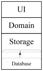
ABC had a strongly architecture-driven development process with a very early-defined overall architecture and continuous efforts to standardize frameworks and detailed sub-architectures. It was assumed that a three-layer (UI, Domain, Storage), two-tier architecture would be appropriate as an overall architecture. A three-layer architecture is a mainstream architecture for OOIS and use-case based development and conceptual modeling strongly encourage an explicit domain layer. The domain layer supports traceability and testing against the conceptual model. In any case, this was a good enough match for requirements that initially the development process could focus on other issues. Most of the deliverables from the use-case based process can directly drive the development of one or more layers in the three-layer architecture. The conceptual model primarily drives the Domain layer and the Storage layer. The UI mockups primarily drive the ultimate UI development. The use cases can drive the testing of both the Domain layer and the UI layer. All of these blueprint flows are primarily forward, but each of the implementation layers can provide important feedback to the blueprinting process and the actual requirements. |
|
The following diagram shows the architecture-level deliverable flow within an increment.
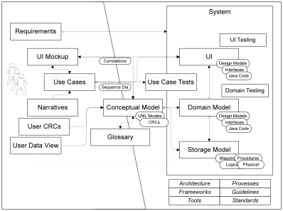
This diagram finishes the specification of the high-level development process.
3.5 Summary
In the previous chapter we only discussed deliverables and made little mention of how people would be involved in developing those deliverables. Now we need to bring people in the process and show how the goals of development, organizational issues, and the team members themselves integrate together.
This chapter begins with a section introducing some concepts for the roles within a development team and is immediately followed by putting team-roles onto the high-level process described in the previous chapter.
4.1 Introduction
This section provides a very high-level introduction of some of the concepts and goals for the roles within a development team. This is to provide context for the more detailed discussion of roles within a ten-person project and to connect to other resources that discuss these topics. These other resources include [Brooks 95, 86], [Booch 94], [XYZ-97], and [… (DeMarco, Constantine, …). The whole section can be quickly skimmed if it seems very familiar.
Notation Description
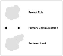
Definitions
|
Project Role |
A set of responsibilities and relationships that one or more individuals can hold. A single individual can hold multiple roles within a project at one moment in time, and role-holders can change during the project’s life. Rarely can the responsibilities within a role go away, so someone must always be officially or unofficially be in a particular role. |
The Simplest Process Model
The simplest approach to building a software system is
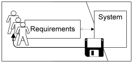
The users state their requirements, and the system is built based on as much of those requirements as it can handle. With this model we simply need two roles: a user and a developer.
Definitions
|
User |
Responsible for describing the process, needs, and wants of the target users. Responsible for evaluating the requirements, blueprints, and system releases. Understands the day-to-day hands-on aspects of the business |
|
Developer |
Responsible for the specification and implementation of the entire system. |
This is a great model for software development[‡‡]: All requirements can be worked out directly between the user and the developer, communication cycles are extremely quick, and there is relatively little chance of long-term miscommunication. The system will have excellent conceptual integrity and will tend to be much more stable and maintainable than if more (non-superior) development resources were added to the task[§§]. There are two severe drawbacks: (1) a single developer will take a long time to develop any significant-sized system, and (2) a single developer will probably initially lack all the necessary development skills required to build certain types of systems (which will compound the previous problem).
The problem is how to scale the development process without losing too many of the benefits from having a single developer do all the work. Or stated another way: how do you make many people’s work appear to be just one (incredibly skilled and productive) person’s work. The question stated this way already leads to its own answer: try to make many people’s work appear to be just one (incredibly skilled and productive) person’s work. The realities of a team and its environment can cause all types of variations on the exact approach, but this unity should always be the goal. The following sections describe one variation for maintaining unity as we scale to a ten-person project.
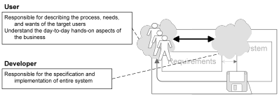
Splitting Specification from Implementation
With the previous high-level model, the Developer role agreed to the requirements and implemented that agreement. If we are to maintain the same level of unity in purpose and not overburden the users with a lot of different people asking inconsistent questions, we will still need a single person overseeing and responsible for the whole specification. Likewise, if the code is to look like it came from one person, we will need a single person overseeing and responsible for the whole development. Finally, if we split specification from implementation we will need someone who maintains the unity of purpose for the whole system: who makes sure specification and implementation meet the goals (time, functionality, resources) of the project as a whole. This gives us a three-way split of our previous developer.
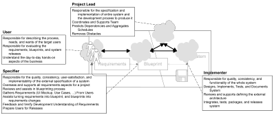
Definitions
|
Project Lead |
Responsible for the specification and implementation of entire system and the development process to produce it. Coordinates and supports development teams. Predicts dependencies and aggregates schedules. Removes obstacles. |
|
Specifier |
Responsible for the quality, consistency, user-satisfaction, and implementability of the external specification of a system. Overseas and supports all requirements aspects for a project. Reviews and assists in blueprinting process. Gathers Requirements (UI Mockup, Use Cases, …) From Users. Assists turning requirements into blueprint, and blueprints into requirements changes. Feedback and Verify Development Understanding of Requirements. Prepare Users for Releases |
|
Implementer |
Responsible for quality, consistency, and functionality of the implemented system. Designs, Implements, Tests, and Documents System. Reviews and supports defining the external architecture. Integrates, tests, packages, and releases system |
As soon as we add more people to a team we need to add roles like the project lead, that continually work on keeping the one-mind property to the project. Depending on the size of the teams and the skills of individuals, a single person could play more than one role, but maintaining the overall unity will be an additional overhead of the team process.
The above roles also have a newer process beneath them that brings in the possible need for a blueprint (both external and internal) shared between the implementers, the specifiers, and the users. This will become especially necessary as we add more team members to the implementation side.
Management
Next we need to take a diversion to put the project in the context of an overall development organization. Organizational management needs to not directly change a project’s goals, but there are many organizational needs surrounding any given project. This connection to other teams, project resources, and upper management are essential.
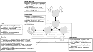
A number of variations can exist for handling management roles and relationships (see [Brooks 97]). The one showed here is a variation that seems closest to modeling the organizational responsibilities placed on XYZ’s group managers (ASMs). A single person can assume both the Group Manager role and the Project Lead role if the managerial responsibilities are light or a particular project does not need much lead activities (i.e. it is self-leading). But because a group manager may have multiple projects, large projects, or recently formed teams, successfully occupying dual-roles is unlikely. Some of the responsibilities defined for the group manager and the project lead can be exchanged or shared.
Roles into Teams
The above model still assumes a single implementer and specifier will be enough for a project. The realities are that many people could be needed to make sufficient forward progress. We can add people to both specification and implementation if these activities are still overseen by individuals and the teams act as one unit. To do this we still have the specifier and implementer (now referred to as architects to match common usage) and they are still responsible for the entire body of work done within their teams. But as their teams grow, they will need to change from being focused on doing the development itself to making sure the team members can do the development.
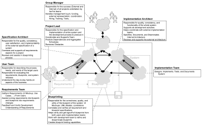
The other scalability change is to have a particular role focussed on making the blueprints, which is a bridging relationship between specification and implementation.
This is the last high-level diagram before returning to the full development process described in the previous chapter.
Summary
The goal of a development team is to produce a system that appears to be written by a single, incredibly talented, and incredibly productive individual. This goal is approached by always keeping overall architectural and project responsibilities in a few roles, and ultimately in a single role. All developers must feel equally responsible for all aspects of the system, and everyone is responsible for building the standards and approaches that will make the team act as a single unit. The role structuring is just to make sure someone is always looking out for these goals and that there is always a unifying solution possible.
4.2 Full Team-Role Model
If we return to our overall deliverable flow from the previous chapter (see section [??]) we can now overlay the team roles onto it. This gives us a full team-role model of the following:
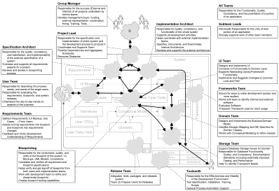
Walkthrough
Most of these roles are the same as in the final version in the introduction. The main differences are: (1) now the implementation architecture is taken into account and several subteams (UI, Domain, Storage, Frameworks) are part of the implementation team, (2) there is a role explicitly for a toolsmith, (3) there is an release subteam, and (4) the team-role model is overlaid on the full use case based flow.
Definitions
Discussion
There are two main reasons to divide the development team roles to match the architectural layering. The first reason is that most developers will not initially be skilled in all areas of a system’s development, so you need to allow them to focus. UI skills are different from database skills and both take time to acquire. The second reason is more important: even if a single developer is able to help in more than one layer of the system, it is important that they do not “cheat” and ignore the architectural layering. An architectural layering is design to make a system more stable and scalable by limiting the ways a system is interconnected. Layering enforces limited knowledge of layers above and of the implementation in layers below. So a developer must make sure to focus first within one layer and not use inappropriate knowledge of another layer to short-circuit the formal interfaces between them. Having separate roles (different hats) reinforces that mentality.
Related to separate layering is the aspect that within any layer there is a single role (the subteam lead) that is responsible for the standards and unity within that layer. The similarity of techniques and code within a layer can be even more strongly reinforced if the subteam has constant encouragement to have a single model.
ABC Specifics
A variation of the above team-role diagram has been in the ABC project from the beginning, but both the current and planned roles have changed over the life of the project.
Different team member’s within the ABC team have different feelings for the process. Some have felt it was too industrialized, where an individual would only see a very small amount of the application. Others feel that focus is good for them, although almost everyone has a desire to rotate through different roles in the project. This rotation would be a good thing for improving the skills and maturity of the team, but because ABC has a tight schedule the rotation has only been done in a couple cases so far. Further rotation will occur in future increments.
4.3 Meter-Rocks: Getting Specific Enough to Manage
The process description so far provides an overview of the concepts, and is detailed enough to know the type of work a team-member would be doing and how that impacts the development of the system. But with a ten-person team it is not detailed enough to be manageable from either an individual’s or the whole team’s perspective. To manage the project we need to get more specific within each of the increments and detail what the internal deliverables are. The internal deliverables are referred to as meter-rocks: they are deliverables sized for intra-team consumption and are smaller than milestones (for between teams) and bigger than inch-pebbles (for an individual developer or a within a subteam).
ABC Specifics
The ABC team identified and defined its meter-rocks over the first few increments. These are documented in detail in documents primarily owned by each of the subteams.
5.1 Risk Management
All projects have many types of risks, which need to be identified, prioritized, and ameliorated for a project to succeed. The ABC process used a variation of the risk management process described in [McConnell 98]. Risk management is divided into specific identification phases and a continuous attempt to find solutions that remove or reduce the risks.
Risk identification, prioritization, and initial antidote-identification is done during the Review and Improve phase of an increment or increment-iteration. The process used is to ask the whole team to contribute and describe new risks that have not identified before. Old risks are also revisited to see if they need a new description. The new input is used to update the complete list and description of risks.
The team is then asked to give each of the risks a weighting from a limited number of total points. These weightings are aggregated together to prioritize the risks (see the ABC Specifics for some discussion of other alternatives). And the resulting ordered list is made public to the team.
Next the team focuses on the highest risks to identify possible antidotes for them. These antidotes are documented and become the input into ameliorating activities during the lifecycle of the next increment.
A final activity would be to review how well the risks were ameliorated in a particular increment, and this can be the first activity in the subsequent review and improve cycle.
Discussion
One important issue in risk management is trust. Can team members really speak out and say what risks are present and brainstorm on what (sometimes-unpleasant) antidotes might work against those risks. This is best solved by making the team feel comfortable, but this can be further augmented by making the risk identification and ranking processes anonymous.
ABC Specifics
ABC has managed risks since Increment-0, and the risk process has always been anonymous based on minority approval. Overall the risk management process seems to be useful: generally our top risks are significantly removed within the next increment/iteration’s cycle, although we also have recurring and cycling risks. It appears the development team feels the top risks are less severe than in earlier increments.
One difficulty ABC is having is getting sufficient participation in the risk identification and ranking. Frequently only 60-70% of the team will contribute to the risk management process. This makes the rankings somewhat unstable. It has also lead to dropping certain activities (like post-increment review) because they were reducing the amount of contribution.
5.2 Success Identification
5.3 Increment Iterations
5.4 Modeling Progression
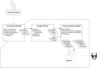
UML supports and defines differing perspectives on a UML software model. There is a progression from the user and requirements oriented conceptual model, through a general specification/design model, and ending in a language and platform-specific implementation model. Depending on the type of model you are looking at, UML notation may mean different things (unfortunately). See [Fowley 98] and [Larman 98] for more information about UML perspectives.
The most important model in the development process is the conceptual model because it is part of the blueprint that binds the development of a system to the users needs. The other models support improved quality and documentation of code, and possible multi-platform implementations of a particular system.
ABC Specifics
The ABC modeling activities primarily focus on the Conceptual Model. The lack of active Design Model activities has several causes. Primary among these is that the ABC architecture is well known and ChiMu already had artifacts to explain major design concepts within it. The ABC architecture document may cause new artifacts to be developed. A second cause is the inability or ineffectiveness of the modeling tools to handle the different modeling translations and ultimate translation to and from code. By bringing in a tool like Together/J, we could have very transparent Implementation Model translation, but this tool seems to still have scalability problems. A third cause is the lack-of-need to translate to other languages. All the designs we have can be specified in terms of Java since it is the only target implementation language.
Type
Types allow you to think about the commonality of objects’ exteriors. They are the first conceptual abstraction above Objects and immediately provide an enormous amount of ability to reasoning about Objects. The amount of abstraction and formality associated with Types can depend on of the project or the current perspective.
Definitions
|
Deliverable |
A defined work product that will be used as the input to another process or released outside the team. Deliverables are documented to describe what receiving parties can expect of them, and they are tracked as part of project management. “Any work product that must be delivered to someone other than the work product’s authors.” [McConnell 98] |
|
Inch-Pebble |
A deliverable used to track progress within a subteam or for an individual. They should generally take a couple days or less. InchPebbles are not used in ABC project management, but are up to individuals and subteams to determine. |
|
Increment |
(1) A portion of a system’s functionality that is built together. Increments limit immediate scope, build upon previous work, and support changes in goals, understanding, and processes during a full project’s lifecycle. (2) The development effort used to build an incremental work product. In the later context, an Increment has defined deliverables and other exit criteria, which will be reached by the processes within the increment. |
|
Increment Product |
A work product resulting from an Increment’s work. |
|
Iteration |
(1) A refinement of an existing work product or process. (2) The development effort within an increment used to bring an increment closer to its exit criteria. |
|
Meter-Rock |
A deliverable that supports tracking progress within a development team and coordination between subteams. MeterRocks are the primary unit to organize activities within an increment. They should generally take about a week to complete. |
|
Milestone |
A large-scale deliverable that is used by external parties to track development progress and coordinate inter-team dependencies. |
|
Release |
An Increment Product that is given to external teams (especially the end users) for their evaluation. |
|
Work Product |
“The tangible result of work performed.” [SPSG] |
|
Deployment |
A release that will go into user production: it will be integrated into the business process and used to record business information. Deployments must be subsequently to prevent harm to the business process and loss of information. |
|
Process |
A collection of tasks that produce deliverables. In this document, processes are performed or controlled by humans: they have the same meaning as in a physical data flow diagram. See [DeMarco 78] |
|
Increment-0 |
An increment focused on preparing the development team to use a particular approach for developing systems. This includes both individual training and group training. |
|
Blueprint |
A specification of what a user desires and what a development team will build. A software blueprint could take many forms, but within ABC it is a combination of UI mockups, use cases, conceptual models, correlation notes, and other requirements documents. |
|
Conceptual Model |
An OO model of the users’ business sufficient to describe the external functionality of a particular system. |
|
User |
Responsible for describing the process, needs, and wants of the target users. Responsible for evaluating the requirements, blueprints, and system releases. Understands the day-to-day hands-on aspects of the business |
|
Development Team |
Responsible for the specification and implementation of the entire system. |
|
Project Lead |
Responsible for the specification and implementation of entire system and the development process to produce it. Coordinates and supports development teams. Predicts dependencies and creates schedules. Removes obstacles. |
|
Specifier |
Responsible for the quality, consistency, user-satisfaction, and implementability of the external specification of a system. Overseas and supports all requirements aspects for a project. Reviews and assists in blueprinting process. Gathers Requirements (UI Mockup, Use Cases, …) From Users. Assists turning requirements into blueprint, and blueprints into requirements changes. Feedback and Verify Development Understanding of Requirements. Prepare Users for Releases |
|
Implementer |
Responsible for quality, consistency, and functionality of the whole system. Designs, Implements, Tests, and Documents System. Reviews and supports defining the external architecture. Integrates, tests, packages, and releases system |
|
Group Manager |
Responsible for the success (External and Internal) of all projects undertaken by her/his teams. Handles management buy-in, funding, external representation, coordination, hiring, training, tools, |
|
Specification Architect |
See specifier. Responsible for getting a team of developers to act like a single specifier. |
|
Implementation Architect |
See implementer. Responsible for helping a team of developers to act like a single implementer. |
|
Toolsmith |
The [Booch 94] |
|
Lead (Subteam) |
Responsible for making sure a subteam works as a single unit and has consistent standards and approaches for developing its deliverables. Subteam leads are responsible for keeping the standards, deliverables, and approach documents up to date. They need to strongly support their team in making forward progress. |
|
UI Team |
|
|
Domain Team |
|
|
Storage Team |
|
|
Release Team |
|
|
Blueprinting Team |
|
|
Requirements Team |
|
